Modern automobiles rely heavily on complex electrical systems to control everything from engine management to infotainment. When an electrical fault occurs, it can manifest as anything from a dead battery to intermittent operation of accessories. Understanding the basic principles of automotive electrical diagnostics can help vehicle owners and technicians systematically identify problems. This article explores common electrical faults, focusing on fuses, relays, and wiring, and demonstrates how a multimeter can be used to trace issues. It also outlines situations where professional assistance may be necessary.
Electrical faults can arise from a variety of causes, including corrosion, loose connections, damaged insulation, or component failure. The diagnostic process typically begins with a clear understanding of the circuit in question and the tools available for testing. A methodical approach not only saves time but also reduces the risk of misdiagnosis. While some issues can be resolved with basic tools and knowledge, others require advanced equipment and expertise. The information provided here is intended for educational purposes and should not replace professional judgment.
Before delving into specific components, it is important to recognize that modern vehicles incorporate numerous electronic modules that communicate over data buses. Faults in these networks can produce symptoms that mimic traditional electrical problems. Therefore, a holistic view of the electrical system is beneficial. The following sections cover fuses, relays, wiring, and the role of a multimeter, along with guidance on when to seek help from a qualified technician.
Understanding Fuses and Their Role in Electrical Protection
Fuses are sacrificial components designed to protect electrical circuits from overcurrent conditions. They contain a metal element that melts when current exceeds a rated value, thereby breaking the circuit and preventing damage to wiring or components. In modern cars, fuses are typically housed in one or more fuse boxes located in the engine compartment, under the dashboard, or in the trunk. Each fuse is assigned to a specific circuit, and its rating is chosen to match the current-carrying capacity of that circuit.
When an electrical accessory stops working, a blown fuse is often the first suspect. However, simply replacing a blown fuse without investigating the cause can lead to repeated failures. A fuse may blow due to a temporary overload, such as a short circuit caused by damaged wiring, or due to a failing component that draws excessive current. Therefore, after replacing a fuse, it is prudent to monitor the circuit for any recurring issues. If the fuse blows again, further diagnosis is required.
Testing a fuse with a multimeter is straightforward. With the fuse removed, set the multimeter to measure resistance (ohms) and touch the probes to the fuse terminals. A good fuse will show near-zero resistance, while a blown fuse will show infinite resistance. Alternatively, with the fuse installed and the circuit powered, set the multimeter to measure voltage (DC volts) and check for voltage on both sides of the fuse. If voltage is present on one side but not the other, the fuse is blown. Always consult the vehicle’s wiring diagram to identify the correct fuse and its location.
Relays: Diagnosis and Testing Procedures
Relays are electromechanical switches that allow a low-current control circuit to operate a high-current load circuit. They are commonly used for components such as fuel pumps, cooling fans, horns, and headlights. A relay consists of a coil, an armature, and contacts. When the coil is energized, it creates a magnetic field that pulls the armature, closing the contacts and completing the load circuit. Relays can fail due to coil burnout, contact wear, or mechanical issues.
Symptoms of a faulty relay include intermittent operation of the associated component, no operation at all, or a clicking sound without the component functioning. To test a relay, begin by locating it in the fuse/relay box. Consult the wiring diagram to identify the coil terminals and the switch terminals. Using a multimeter, you can perform several checks. First, measure the resistance of the coil; it should typically be between 50 and 120 ohms, depending on the relay. An open coil (infinite resistance) indicates a failed relay. Next, check the switch contacts: with the relay de-energized, there should be no continuity between the common and normally open terminals, and continuity between common and normally closed terminals (if applicable).
To test the relay under power, you can apply voltage to the coil terminals using a suitable power source and listen for a click. Then, with the multimeter set to continuity, check that the contacts close. Alternatively, you can use a relay tester, which simplifies the process. If the relay does not function as expected, replacement is usually the solution. However, always verify that the control circuit is providing the correct signal before condemning the relay.
Wiring and Multimeter Techniques for Fault Tracing
Wiring is the network of conductors that connects electrical components. Over time, wires can become damaged due to heat, vibration, chafing, or corrosion. Common wiring faults include open circuits (broken wire), short circuits (wire touching ground or another wire), and high resistance due to corrosion. These faults can cause a variety of symptoms, such as dim lights, slow motors, or intermittent operation.
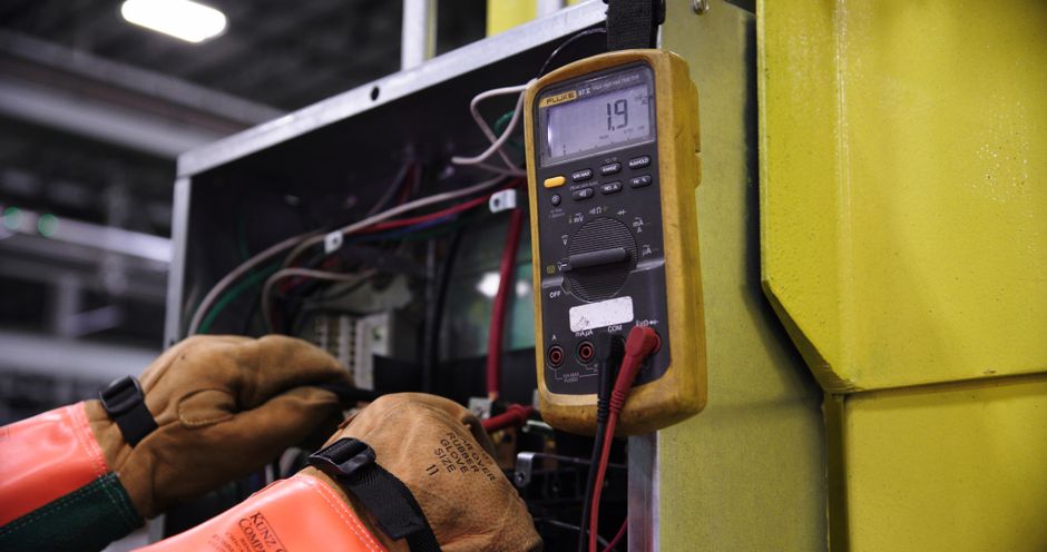
A multimeter is an essential tool for tracing wiring faults. It can measure voltage, resistance, and continuity. Before testing, ensure the multimeter is set to the appropriate function and range. For voltage checks, connect the black probe to a known good ground and the red probe to the point of interest. For resistance or continuity checks, disconnect power to the circuit to avoid damage to the meter. A continuity test can quickly identify open circuits: if the meter beeps or shows near-zero resistance, the wire is continuous; if it shows infinite resistance, the wire is broken.
When tracing a short circuit, isolate sections of the wiring harness by disconnecting connectors. Measure resistance between the suspect wire and ground; a short will show low resistance. Another technique is to use a fused jumper wire to bypass sections of the circuit. Always refer to the wiring diagram to understand the circuit layout and expected voltages. For intermittent faults, a wiggle test—moving the harness while monitoring the multimeter—can help locate the problem area. Patience and systematic elimination are key.
When to Seek Professional Help
While basic electrical diagnostics can be performed by a knowledgeable vehicle owner, certain situations warrant professional assistance. Modern vehicles are equipped with numerous electronic control units (ECUs) that communicate over networks such as CAN bus. Faults in these systems may require advanced diagnostic tools like oscilloscopes and scan tools to read fault codes and analyze data streams. Attempting to diagnose complex network issues without proper equipment can lead to further damage or misdiagnosis.
Additionally, if a fault involves high-voltage systems, such as those in hybrid or electric vehicles, it is crucial to seek a qualified technician. High-voltage systems can be lethal if not handled correctly. Other signs that professional help is needed include recurring fuse failures after replacement, multiple electrical systems malfunctioning simultaneously, or the presence of burning smells or smoke. These may indicate serious underlying issues that require expert attention.
Auto Insight emphasizes the importance of understanding one’s limitations and utilizing professional services when appropriate. A certified technician has access to manufacturer-specific service information, training, and tools that enable accurate diagnosis and repair. While this article provides a foundation for troubleshooting, it is not a substitute for hands-on experience and formal training. Always prioritize safety and consider consulting a professional when in doubt.
Conclusion
Diagnosing electrical faults in modern cars involves a logical approach, starting with fuses, relays, and wiring, and utilizing a multimeter for testing. By understanding the function of each component and following systematic procedures, many common issues can be identified and resolved. However, the complexity of modern electrical systems means that some problems are best left to professionals. Whether you are a DIY enthusiast or a vehicle owner seeking to understand your car better, a methodical and safety-conscious mindset is essential. Always refer to the vehicle’s service manual and wiring diagrams, and never hesitate to seek expert help when needed.